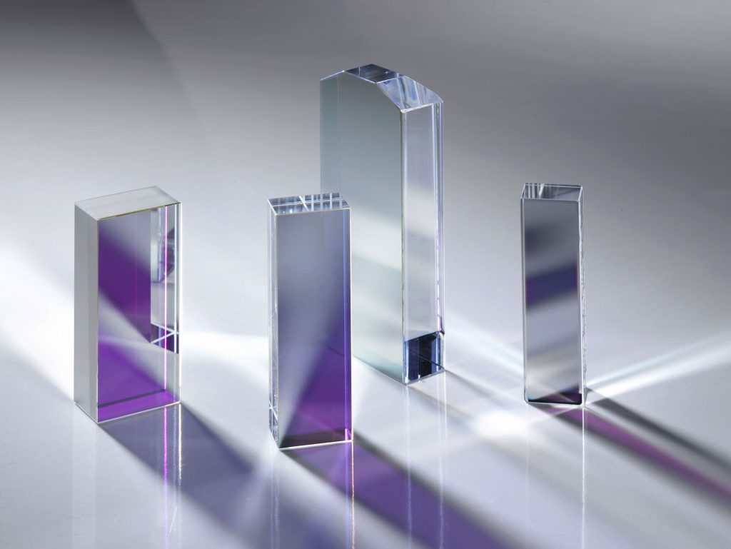
VIS 50R/50T Non-polarising Beamsplitter Cube
VIS 50R/50T Non-Polarizing Beamsplitter Cube Coligh manufactures is designed to equally divide incident light into 50% reflected and 50% transmitted beams across 400–700 nm.
- 50% Reflection / 50% Transmission (±5%)
- Optimize for 400-700nm wavelength range
- Non-polarizing Design
- Cube format
- Also available for NIR 700-1100nm and SWIR 1100-1600nm
Products Categories
Get A Free Quote
Dielectric Coated 50R/50T Cube Beamsplitter for 400–700nm Description
The VIS 50R/50T Non-Polarising Beamsplitter Cube is a precision optical component designed to split an incident beam into two beams—reflected (R) and transmitted (T)—each carrying approximately 50% of the original intensity across the visible spectrum (typically 400–700 nm).
- The cube structure is formed by cementing two high-precision right-angle prisms, ensuring excellent surface flatness, angular tolerance, and minimal wavefront distortion to maintain beam quality. Compared with plate beamsplitters, the cube design eliminates lateral beam displacement and double images (ghosting), simplifying optical alignment.
- A metal-induced beamsplitting coating is applied on the internal diagonal surface, and broadband anti-reflection coatings are applied to all four input/output faces to preserve the polarization state of the output beam and enhance transmission.
- The broadband AR coatings on the four external surfaces significantly reduce surface reflection losses, increase overall light throughput, and minimize stray light and ghosting.
VIS 50R/50T Non-polarising Beamsplitter Cube Technical Datasheet
| Parameter | Specification |
| Wavelength Range | 400–700 nm |
| Reflection / Transmission | 50% / 50% ± 5% |
| Angle of Incidence (AOI) | 0° (normal incidence) |
| Coating Type | Dielectric non-polarizing beamsplitter coating The bevel is coated with depolarizing spectroscopic film The output and incident surfaces are coated with anti-reflection film |
| Polarization Sensitivity | < 6% variation between S and P polarization |
| AR Coating | Broadband AR on all entrance/exit faces @45+/-5% (400–700 nm) |
| Absorption | <10% |
| Substrate Material | K9 |
| Surface Quality | 60-40, 40-20 scratch-dig (MIL-PRF-13830B) |
| Surface Flatness | < λ/4 @ 632.8 nm |
| Beam Deviation | < 3 arcminutes |
| Clear Aperture | >90% of each face |
| Construction | Cemented right-angle prism pair |
| Laser Damage threhold | >100mj/cm², 20ns, 20Hz @1064nm |
| Other Available R/T Ratios | 10R/90T, 30R/70T, 70R/30T, 90R/10T |
| Available Sizes | 5×5×5mm to 50*50*50mm or custom |
VIS 50R/50T Non-polarising Beamsplitter Cube Applications
- Laser Power Distribution and Optical Path Management
In dual-channel laser experiments, it is necessary to equally split a single laser beam into two paths without altering its polarization state. By directing the laser perpendicularly into a non-polarizing beamsplitter cube, both the transmitted and reflected beams receive approximately 50% of the original intensity with no polarization dependence. This preserves the laser’s polarization integrity and avoids the polarization losses caused by traditional polarizing beamsplitters. - Michelson Interferometer
Interferometers require the reference and measurement arms to have equal light intensities (50/50 splitting) and matched polarization states to prevent fringe contrast degradation. Placing a beamsplitter cube at the center of the interferometer’s optical path divides the input beam into two orthogonal paths that recombine to form interference. This ensures balanced intensity between the two arms and enhances fringe visibility. - Optical Teaching and Demonstration Experiments
In optical experiments such as beam splitting verification and path combination, a clear 50/50 split with minimal polarization effects helps students intuitively understand the principles. By directing a white light LED or laser source into a beamsplitter cube, students can directly observe the intensity and color consistency of the transmitted and reflected beams. - Optical Feedback Control
In laser frequency stabilization or optical phase-locked loop systems, part of the laser output must be extracted for feedback without being affected by polarization fluctuations. A beamsplitter cube at the laser output directs 50% of the beam to a photodetector for feedback control, while the remaining light proceeds to the main system. This suppresses polarization-induced feedback signal drift, enhancing system stability.